


Electric Ball Control Valve Installation Guide
Introduction
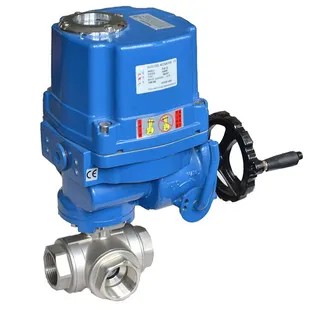
Electric ball control valves are essential in industrial, commercial, and residential fluid systems, offering precise, automated control. Proper installation is key to ensuring performance, longevity, and operational safety.
This step-by-step guide outlines pre-installation checks, electrical wiring, and final testing procedures. Whether you're a technician, engineer, or hands-on professional, following this guide will help you avoid common errors and ensure optimal valve operation.
Pre-Installation Guidelines
1. Review Safety Instructions
- Read the manufacturer’s manual thoroughly.
- Ensure all personnel are trained on safety protocols, especially regarding electrical hazards and pressurized systems.
2. Verify Valve Specifications
Check the actuator’s label for:
- Pressure rating (e.g., maximum allowable pressure)
- Temperature range
- Media compatibility (chemical resistance of valve materials)
Refer to documentation if specifications are unclear.
3. Choose the Installation Location
- Select a dry, sheltered area to protect the actuator from moisture and environmental hazards.
- Ensure sufficient space for maintenance access.
- Avoid exposure to vibration, corrosive agents, or high mechanical stress.
4. Depressurize and Cool the System
- Shut off fluid supply and relieve residual pressure.
- Allow the system to cool down if hot fluids are involved.
5. Inspect and Clean Piping
- Remove any debris, scale, or corrosion from the piping.
- Clean using flushing or compressed air to prevent operational blockages.
6. Install a Filter (If Required)
- Use a filter or strainer upstream to prevent particle damage to the valve.
- Clean or replace the filter regularly.
7. Gather Tools and Materials
Tools:
- Adjustable wrench or appropriate spanners
- Pipe thread sealant or PTFE tape
- Wire strippers and screwdrivers
- Crimping tools or ferrule set
- Welding tools (for welded connections)
Fittings:
- Threaded, flanged, or welded adapters (per pipe type and system design)
Wiring the Electric Actuator
1. Locate the Wiring Diagram
- Refer to the actuator’s manual or housing label for the correct wiring schematic.
- Confirm model compatibility (AC/DC, voltage rating, control type).
2. Prepare the Wires
- Strip 6–8 mm of insulation from wire ends.
- Use ferrules or crimp connectors for enhanced reliability in industrial settings.
3. Connect Power Supply
- AC Actuator Example:
- L (Live): Connect to hot wire (120V/240V)
- N (Neutral): Connect to return
- G (Ground): Connect to earth ground
- DC Actuator:
- Match + and – terminals with corresponding power leads.
4. Control Signal Wiring
- Manual control: Use NO (Normally Open) and COM (Common) for switch operation.
- Automated control (e.g., PLC):
- Use 4–20mA or 0–10V signal terminals.
- Ensure proper polarity and shielding.
5. Secure All Connections
- Tighten terminal screws to prevent loosening from vibration.
- Use cable glands or strain relief fittings for all wire entries.
6. Test the Actuator
- Power the system and send a control signal.
- Observe rotation:
- Clockwise = Closed
- Counter-clockwise = Open
- If non-responsive:
- Check for voltage.
- Confirm signal configuration.
- Inspect for mechanical jams.
7. Final Inspection
- Ensure no exposed wires or damaged insulation.
- Confirm that the actuator enclosure is fully sealed (e.g., IP65/IP67 rating).
- Monitor for excessive heat during the first run.
Installation Best Practices
1. Ensure Alignment
- Align pipes before tightening to avoid axial stress.
- Use flexible couplings when thermal or mechanical pipe movement is expected.
2. Avoid Over-Tightening
- Follow the manufacturer’s torque specifications for flanged or threaded joints.
3. Plan for Maintenance
- Schedule periodic checks for:
- Electrical connection integrity
- Response time consistency
- Visual wear or corrosion
Conclusion
Installing an electric ball control valve correctly ensures safe, efficient, and trouble-free operation. From site preparation and mechanical mounting to electrical wiring and final testing, each step is crucial to long-term performance.
Tip: Always refer to the manufacturer’s installation manual for specific wiring diagrams and torque values.
By following these best practices, you can prevent early failure, reduce maintenance costs, and enhance system reliability. Know more about Google SEO Directory
Comments