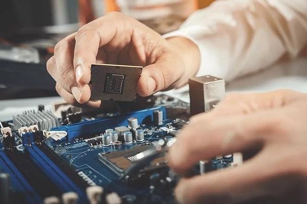
Printed Circuit Boards (PCBs) are the backbone of modern electronics, serving as the foundation for countless devices we use daily. From smartphones to industrial machinery, PCBs are integral components that enable the functionality of electronic systems. In this article, we'll delve into the world of PCB circuits, exploring their significance, basic structure, and the process of designing and manufacturing them.
Understanding PCB Circuits
At its core, a placa PCB is a flat board made of a non-conductive material, usually fiberglass, with conductive pathways etched or printed onto its surface. These pathways, typically made of copper, form the electrical connections between various components mounted on the board. The layout of these pathways is designed using specialized software, taking into account the specific requirements of the electronic device.
Basic Components of a PCB Circuit
Substrate: The base material of the PCB smt, often referred to as the substrate, provides mechanical support and insulation for the circuitry. Common substrates include fiberglass (FR-4) and flexible polymer materials.
Conductive Traces: Copper traces are used to create electrical connections between components on the PCB. These traces are etched onto the substrate using a chemical process or deposited using specialized printing techniques.
Components: Electronic components such as resistors, capacitors, integrated circuits (ICs), and connectors are mounted onto the PCB and connected by the conductive traces. The arrangement of these components is determined by the circuit design.
Solder: Solder is used to secure components onto the PCB and create electrical connections between them and the conductive traces. Surface-mount technology (SMT) and through-hole technology (THT) are the two primary methods of soldering components onto PCBs.
Designing PCB Circuits
Designing a PCB circuit involves several steps, starting from conceptualization to the final layout. Here's an overview of the design process:
Schematic Design: Engineers create a schematic diagram of the circuit, depicting the interconnections between components using symbols and lines. This serves as a blueprint for the physical layout of the PCB.

PCB Layout: Using specialized software, engineers translate the schematic into a physical layout, positioning components and routing traces to optimize performance and minimize interference.
Design Verification: The design is then subjected to rigorous testing and simulation to ensure functionality, reliability, and adherence to design constraints such as signal integrity and thermal management.
Manufacturing Files: Once the design is finalized, manufacturing files containing information about component placement, trace routing, and drill locations are generated and sent to PCB fabrication facilities.
Manufacturing Process
The manufacturing process typically involves the following steps:
Substrate Preparation: The base material is prepared by cutting it to size and cleaning its surface to remove any contaminants.
Copper Deposition: A thin layer of copper is applied to the substrate using techniques such as electroplating or lamination.
Photoengraving: A photosensitive layer called the resist is applied to the copper surface, and the desired circuit pattern is transferred onto it using a photographic process. The unwanted copper is then etched away, leaving behind the conductive traces.
Drilling: Holes are drilled into the PCB at specified locations to accommodate component leads and mounting hardware.
Component Assembly: Electronic components are placed onto the PCB using automated pick-and-place machines, and soldered into place using reflow soldering ovens or wave soldering machines.
Testing and Inspection: The assembled PCBs undergo rigorous testing and inspection to ensure functionality and quality standards are met.
Conclusion
PCB circuits are fundamental building blocks of modern electronics, enabling the creation of complex electronic systems in a compact and reliable form factor. Understanding the basics of PCB design and manufacturing is essential for engineers and designers looking to develop innovative electronic devices that push the boundaries of technology. With advancements in manufacturing processes and design tools, the possibilities for PCB-based solutions are endless, driving innovation across various industries.


Comments